Showing posts with label Beginner. Show all posts

AIRCRAFT CONTROL SYSTEMS - Part 2

In Part 1 we cover most of the important control, they are:
Ailerons
Rudder
Elevators


Here in Part 2 I will continue in other control surfaces.

Before that I shall introduce this formula to you - The Lift Equation (Extracted from NASA. (https://www.grc.nasa.gov/www/k-12/airplane/lifteq.html)
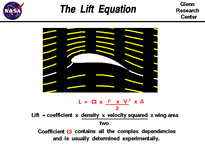
Computer drawing of an airfoil. Lift equals the lift coefficient
 times the density times the area times half the velocity squared.

Lift is generated based on these factors.

Coefficient - It is based on Wind Tunnel Testing and Simulation to derive the lift coefficient for each wing design.

Density - It is referring to the air density. The higher the altitude the lower the density. Just picture this (Refer to the previous Part 1 video). The higher the density the more molecules in the air.

Velocity - The speed relative to the airflow

Wing Area - Self explanatory. You might think that "Let's make the biggest wing and will produce more lift!" Yes, you are half correct but at the same time you will introduce more drag as well.

So we need to strike a balance to maintain the Lift to Drag Ratio.

The wing shape is the most crucial and costly part of the plane design, it takes billion dollars to R&D a new wing. So don't play play.


Slats & Flaps:

Slats are additional lifting devices installed on or inside the wing's leading edge. (See Fig.2)
The idea is to increase the wing camber. The slats control normally is hard wired together with the Flaps, the Slats as it has only one position and normally tied with the first flaps setting. The slats can dramatically reduce the take-off and landing distance. It helps to lower the nose, so that the pilot can have a better take-off and landing view without increasing airspeed.

Flaps are additional lifting devices installed on or inside the wing trailing edge. (See Fig.3 & 4) The idea is to increase the Wing Area and camber. The Pilot in the cockpit control the flaps by putting the Flaps into the desire slots.

Different OEM will have different calling. Boeing will have the flaps settings in °; e.g. 1°, 5°, 15°, 30°,  40° while Airbus will have the setting in number. e.g. Flaps 1, 2, 3, Full.
Fig. 1-4 Showing varies stages of Slats and Flaps configurations
Control:
The control is located inside the cockpit (See Fig.5 & 6 - Airbus A320) normally on the central pedestal. And it is control by a stick with different position settings. The pilot have to observe the designed extension and retraction speed of the flaps. e.g. when the airspeed over the Vfe, the flaps might be damaged by strong speed.

Fig.5 - Airbus A320 Cockpit
Fig.6 - A320 FLAPS Lever
Effect on flying:
When the slats and flaps are extended, the aircraft will tend to ascend due to the extra lift and hence the pilot will have to push the yoke to lower the nose. The benefit of this will give the pilot a better field of view for their take-off and landing.

Normally, during take-off the flaps setting will be 1 or 2 because 3 onward though give you more lift but it also create more induce drag.

During landing the extra drag is actually plus points therefore they will normally use Flaps 3 or Full for landing.


Trims:
Imagine when you are flying an aircraft and you have to hold on to the yoke or side stick for minutes, that is a very tiresome move and it stresses the pilot physically. Therefore the solution is trim. (See fig.7)

Fig. 7 - Trim tabs (Tail view)

There are three trim tabs installed on Elevators, Ailerons, and Rudders. (See picture) The trim tab is adjusted by a trim wheel, or switch installed in cockpit to adjust to the desire outcome. With that the pilot is able to fly the plane "hands-free". Do take note that during take-off and landing, you have to adjust the trim back to the acceptable trim range. In case of emergency, if your trim is not within the acceptable range, the plane will not response enough to your desire input.

Fig. 8 - Trim tab in action. It is adjusted by trim wheel in cockpit

Engines a.k.a. Power Plants:
Without engines the plane will not fall out of the sky but the plane will become a giant glider. The engine is important to produce power to either push or pull the plane forward. That resulted in the Lift Formula "V" component. The faster it is the more lift it can generates.

Engine configurations are many, like single piston propeller to supersonic jet engine. In terms of efficiency, the piston or turbo propeller configuration is more suitable for lower altitude (1000 ft to FL280) range.

The Jet engine is more efficient in higher altitude (FL250 - FL510) because of low air density (low drag, high rpm).

There are single, twin, triple and quad engines configurations. In these days twin engines configuration is the norm due to increase engine reliability and fuel-consumption friendly.

Flight Control:
In airliner, the engine is govern by 2 x FADEC (Full Authority Digital Engine Control) computer and is 100% digital control (No more mechanical wires and cables).

In a turbo-fan engine we have measurement from N1 & N2 and they are measured in terms of percentage.
N1 is talking about stage 1 fan speed and N2 is talking about compressor stage fan speed. The throttle quadrant is the pilot input to control the fan speed.
In modern day airliners, speed control is by the FCS (Flight Control System) also part of the Auto-pilot. The pilot just need to input the desire speed and the FADEC will control the engine to the required speed.

I have over simplified things here but maybe in future I will dedicate one single session about power plant.

During all sorts of control failures, and left only with engines control you can still control the plane by adjusting engine power.

To climb, just add more power to the engine.
To descend, just reduce power.
To turn left, just increase starboard side power and reduce port side power.
To turn right, do the opposite.
AIRCRAFT CONTROL SYSTEMS - Part 1

This video is about aircraft control systems: Ailerons, Elevators, and Rudder
Systems introduced:
Aileron = Yoke / Stick steer left or right
Elevator = Yoke column / stick pull up or push down
Rudder = Rudder pedals kick left or right


The primary control in-flight is the Yoke and rudder System (Or Stick and Rudder, or Horn and Rudder). Traditionally they are linked with cables, pulleys and assisted by hydraulics but these cables are heavy and added a lot of weight to the aircraft.

With advance in technology, we could use electronic sensor to calculate the pilot inputs and compute the required movements. With this changes, we can now save tons of weight by replacing steel cables and pulleys by shielded electrical wire and 3 computers.

History of Fly-By-Wire:
The first fly-by-wire (FBW) system were invented in 1964 by USA for there Apollo Lunar Landing Research Vehicle (LLRV). Then subsequently the FBW systems were used in Fighter Jets.

The first commercial FBW aircraft is the Concorde. And the first sub-sonic (Less than Mach 1.0) aircraft using FBW is Airbus A320.

Let's talk about Axis:

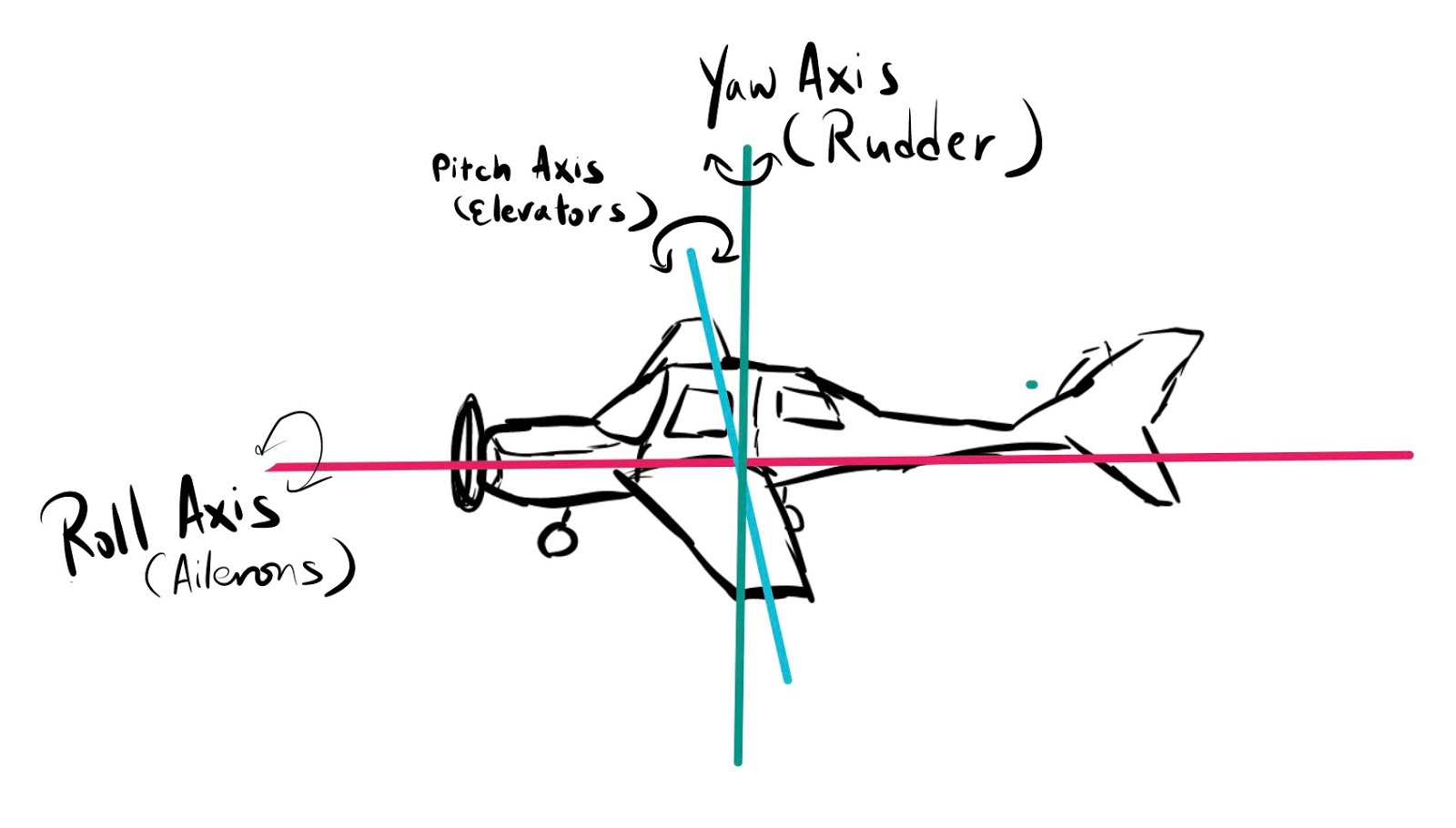
There are 3 imaginary lines cutting across the aircraft pivot point. And from the pivot point they extend on vertically, horizontally and longitudinally.

From Fig.1 you can see the Red Axis cutting along the aircraft from front to back. This axis called Roll Axis (a.k.a. longitudinal axis), the resultant of this axis is rolling and it is controlled by the ailerons.

The Blue Axis cutting along the wing from port side to starboard side. This axis called Pitch Axis (a.k.a latitudinal axis), the resultant of this moment is pitching and it is controlled by the elevators.

The Green Axis cutting along the fuselage from bottom to top. This axis called Yaw Axis (a.k.a. normal axis), the resultant of this moment is yaw and it is controlled by the rudder.


AIRCRAFT COMPONENTS - INTERIOR (BASIC)

Did some hard work in editing here, enjoy this lesson. Leave me a comment if you like it!


Navigation / Communication Panel

Nav/Com Selectors:
To select the active radio for communication, you can listen and transmit. Alternatively you can select both but only able to transmit on either Comms 1 or 2. The benefits is enable you to listen to 2 frequencies. e.g. ATIS + Tower; Radar Control + Tower.. etc.

Nav. Selector:
Will activate the selected navigational aids identification sound. Morse code will be transmitted and for you to listen and identify the tuned in station i.e. VOR (VHF Omni-Directional Radio) or ILS (Instrument Landing System). On your navigation chart each VOR, ILS will have its unique Morse code for identification.

Radio Panel:
For you to tune in to the station frequency. Left side for Comms and Right side for Nav.
Comms frequency range from 118.00 - 132.00 MHz. Tuning frequency by rotating the knobs, big knob for last digit adjustment i.e. 11X.00. Small knob for decimal adjustment i.e. 118.xx. Increment with .25 or .50 MHz spacing

Nav frequency range from 108.00 -117.95MHz. Tuning frequency by rotating the knobs, big knob for last digit adjustment i.e. 10X.00. Small knob for decimal adjustment i.e. 108.xx. Increment with .25 or .50 MHz spacing

When you turn the knob will only adjust the standby frequency and will not change the active frequency. Therefore you have to click the switch <- -=""> to swap between the active and standby frequency.

ADF (Automatic Direction Finder) Panel:
For you to tune in to the NDB (Non-Directional Beacon) Transmitter. Once in range, the ADF instrument - An arrow (Not shown here) will point to the NDB Transmitter.
NDB is phasing out since it is not a very informative navigational aid comparing to VOR/DME. NDB only provide relative direction.

DME (Distance Measuring Equipment) Panel:
For you to readout the DME distance. You don't really need to tune the DME frequency as normally it is paired with the VOR frequency. Meaning you just need to tune your NAV frequency to the VOR and the DME will work together. Please note that not all VOR have DME together, there might be some station with VOR only. Check your map symbols.

Transponder:
This is for you to dial-in the squawk code assigned by ATC (Air Traffic Control), the squawk code will appear on the ATC radar and they use the code to identify you. And when they request you to IDENT yourself, simply push the IDENT button. With this action your aircraft will blink on the ATC Radar.

Auto-pilot Panel:
Most of the GA (General Aviation) will not have this. But with this you can set it to your desire altitude, climb / descend rate, heading and etc. And with a push of a button, you can fly hands-free.

BASIC SIX

Air Speed Indicator:
To show your current airspeed, the source is from the pitot tube located outside of the aircraft. (Read my Aircraft Components - Exterior Post)
There are different color bands to indicate different limits. There is a red line at the end of the dial, that's your maximum speed of your aircraft and you shall not exceed it in any case.
White Arc - Flaps operational range
Green Arc - Normal operational range
Yellow Arc - Caution range (Only can operate during smooth air)

Turn Coordinator:
This helps you on your turn, when you are flying a coordinated turn, you are flying a perfect arc there is no slip or skid. (Think about it on car drafting, under-steer or over-steer)
The ideal turn is bank your aircraft to touch the left/right 2nd white line and keep the ball in the center of the 2 bars. (My instructor taught me "Keep the bad guy in jail")

Attitude Indicator:
We call it artificial horizon, it shows you the real time attitude of the aircraft. The Bank and Pitch angles. It is utmost important when you fly IFR (Instrument Flight Rule) since you can reference yourself to the actual horizon.

Horizontal Situation Indicator (HSI):
It is your primary compass and it integrates VOR direction. We will talk more during our aircraft navigation course.

Vertical Speed Indicator (VSI):
By using the input source  Pitot-Static, it can display the current rate of ascend and descend in feet per minute. Normal landing vertical speed is within -300 ft/min to preserve the landing gears.

Altimeter:
The important instrument to tell you how high you are relative to mean sea level (QNH - Mean sea level air pressure) or to the airport elevation (QFE - airport air pressure). Your tower controller or ATIS will have this QNH/QFE value, once you have this value you can adjust your altimeter and it will show the correct altitude.

Swithces

Electrical:
Your aircraft needs electricity for both instruments, radios, lighting, and your iPad/iPhone. Therefore we have battery on-board. For large aircraft, batteries are only for emergency use, normally they will use engine power to power the generators.

Anti-Ice:
Switch it on to prevent icing formation on critical parts of the aircraft. e.g. Wings, pitot tubes, static ports, engine inlets and etc.

Magneto:
Is the spark plugs for your engines. (Does not exist in larger or jet engines) There are 2 circuits, so in case 1 failed you still have another. The circuits separated to Left and Right, during normal operations will be using both. When turn to start, it will crank the engine to start.

Lighting:
To switch on different exterior and interior lights.

Air-Con:
For non-pressurized aircraft, this is just like an air-con for car. For pressurized aircraft, you might have to adjust the setting to get the optimum cabin pressure. Will talk about it during cruising lesson in future.

Throttle quadrant:

Throttle:
To adjust the speed of the propeller. 

Propeller pitch lever:
To adjust the pitch angle of the propeller so that you can achieve better fuel cruise performance.

Fuel Mixture lever:
To adjust the air to fuel mixture proportion, we call it leaning. As you climb higher, the air get thinner and you need to adjust fuel mixture to give you a longer range cruise. But if the fuel is significantly less than air, the engine will flame out or the engine will be running very hot (Fuel can cool the engine). So need some fine touch on that.

Flight Control:

Yoke / Yoke Stick:
Depends on the aircraft manufacturer, you can have either Side Stick / Yoke / Yoke Stick (Cessna 162) / Motorcycle Bar (Embraer). When you turn the yoke to left / right, it translates it to roll and bank by activating the ailerons. When you push or pull the yoke, it translate to nose down or nose up by activating the elevator.

Rudder Pedals:
You use your leg to control, one leg one pedal (different from car). When you extend your left leg and push the left rudder pedal, the right rudder pedal will travel in opposite direction. Therefore only on pedal can be pushed or pull at any one time. 

The left pedal will yaw left and right pedal will yaw right. Simple! And to keep the bad guy in jail, kick the left pedal when the bad guy goes left. Right pedal when the bad guy goes right. Hahah...

Flaps:

To extend and retract the flaps. 

Landing Gear Lever:

To extend or retract the landing gears. There are 3 green lights next to it to indicate the status of the landing gears. When it is down and locked, 3 greens will illuminate. Otherwise, the 3 greens are extinguished. 

Aircraft Components - Exterior (Basic)

Loading time for this page will be slightly slow as there are many Animated GIFs.
------------------------------------------
This time let us walk around an aircraft and I will identify each part and tell you what is the function briefly (Since this is the beginner course).

The aircraft models used here consist of:
B737, B777, B747 (Air Force 1 livery) and Phenom 300
Try to identify them!

Aircraft is assembled out of these parts:

1. Fuselage - 
It is the main body of the aircraft. It house the passengers, crew and payload. All the other components are welded or insert to the fuselage to form the entire aircraft.

Function:
To carry and protect passengers and cargo. It is the center of aircraft assembly.


2. Wings a.k.a. main lifting device - 
The wings provide Lift to keep the aircraft in the air. Without it, the aircraft will not be able to sustain in the air. Unless it is equipped with rocket engines which the thrust is much greater than the weight. There are many wing designs which I will talk about it in details in the future post.

Function:
It is to provide the main lifting force for the aircraft to fly in the air.


3. Horizontal Stabilizer - 
This part including the elevator which is designed to control the pitch moment of the aircraft. Without this, the aircraft will go crazy into climb or descend depends on the Center of Gravity at that moment.

Function:
It is to provide pitch/longitudinal stability.


4. Vertical Stabilizer - 
Consists of the tail fin and the rudder. The idea of calling them stabilizer is because they are the important parts to stabilize the aircraft in-flight. To keep flying straight and level. Without any of the stabilizer, the aircraft will be "Unstable" and difficult to control.

Function:
It is to provide yaw/normal axis stability.


5. Empennage (i.e. tail assembly = Vertical + Horizontal Stabilizer) -
This is just a name and is mainly used on fighter jets as they have short and narrow fuselage.

Function:
It is to provide overall stability of the aircraft.


6. Power Plants a.k.a. Engines - 
Without these 2 engines, the aircraft becomes a glider.
One Engine can produce enough thrust to support entire aircraft in the air, of-course it can't fly high and fast enough for the entire flight, therefore a diversion is required if one engine is not operative.

Nowadays Engine is designed to have a high-bypass ratio (Turbo-Fan) which means it can move a large quantity of air molecules in a short-time. In the past, jet engine (Turbo-Jet) is accelerating small amount of air molecules to extremely high speed in order to produce thrust. The current high-bypass ratio engine can achieve the same thrust by move a large amount of air molecules in a short-time. The benefits is much quieter and cooler engine.

Function:
It is to produce thrust.


Flight Control Systems:

In general, there are 3 moments in flight: 
- Pitch (along latitudinal axis)
- Roll (along longitudinal axis)
- Yaw (along normal axis)
And these are the control surface to change the state of one or more of the followings. In the coming lesson I will explain all the relationship, but here we learn where they are and what they called.

1. Aileron - 
The Aileron is part of the wing but this is a moveable part, it is pivoted to the wing and moves upward and downward. There is Aileron on left and right wings, however their movement is the opposite of each other.

i.e. The left aileron moves upward, the right aileron to move downward.
The left aileron moves downward, the left aileron will move upwards.

Function:
To roll/bank the aircraft along longitudinal axis.
The moving parts here are only outer aileron! There is another inner aileron, which also act as a Flaps. Some called it Flaperon.


2. Elevator -
The Elevator most of the time is located at the back of the aircraft and is part of the horizontal stabilizer. It pivoted to the horizontal stabilizer and only move upwards and downwards together. Unlike the aileron, they move in the same direction.

Function: The Elevator is to change the pitch of the aircraft along the latitudinal axis and there are 3 states: Level, Nose Up and Nose Down.


3. Rudder -
It is part of the vertical stabilizer. The rudder pivoted along the vertical stabilizer and the movement is left and right.

Function: It is to control the yaw (Nose Left or Nose Right) of the aircraft along the normal axis.


4. Slats, Flaps and Pylons - 
Flaps and Pylons are an additional lifting device and formed part of the wing installed at the trailing edge of the wing. It is to be used during slow speed such as during takeoff and landing. During cruise, the flaps will be retracted (Hidden inside the wing). The pylons is the mechanism to extend and retract the flaps. More lift is generated when the flaps is extended. The flaps extend backward increase the wing surface, it also can be extended downwards to increase drag (For landing use).

Slats is an additional device and formed part of the wing. It is installed at the leading edge of the wing and when extended it will increase the camber of the wing shape to make it more suitable for slow flight. During cruise, the slats will be retracted to minimize drag since cruising speed is much higher and does not require additional lifting device.

The Slats might not be present in all aircraft, Boeing and Airbus Jetliners will have it. But probably not in smaller size aircraft and General Aviation.

Function: It is to provide extra lift and drag.
Flaps In Action

Slats Increase Wing Camber (Not actual slats - for illustration only)


5. Multi-function Spoilers -
The multi-function spoilers has 2 uses, one in the air and one on the ground therefore the name multi-function.

Speed Brakes - When it is used in the air, there are 2 functions. Primarily this is by extending these panels upwards (Not more than 20 deg) to increase the drag and hence the speed reduction. Secondary function will be acted as assisted aileron to help the aircraft in bank and roll.

Ground Spoiler - When it is used on ground, the only function is during landing and rejected takeoff. These panels will fully extended upward around 80 degrees, the theory is to break the airflow and create a "Lift Dump" effect. In this case the landing gears will have more traction and friction on ground for more effective braking.


Systems:

1. Pitot-Static or Pitot and Static - 
In older aircrafts they are separated ports. The Pitot Tube must be in the front of the aircraft to and facing forward in order to capture the airflow.
The Static port need to be installed at the least airflow disturbance area, most of the time will be by the side of the fuselage. And flushed with the fuselage surface.

Pitot Tube's function is to measure the air pressure inside the pitot tube
Static Port's function is to measure the static pressure.
The air data computer then will compare 2 of the inputs using a formula and deduct the the Airspeed, Altitude and Vertical Speed. (We will have a detailed lesson about this in coming lessons.

In more advanced aircraft they have Smart Probe which combines Pitot-Static, Temperature Sensor and Angle of Attack all in one. It is easier and faster for maintenance as well but the cost price of one probe is much higher.


2. Anti-ice - 
There are multiple parts equipped with anti-ice system. They are Windshield, Wings' leading edge, Elevators' leading edge and Engine Inlets.

There are few anti-ice systems available:
1. Ice-boot (Cheapest implementation) - Is made of rubber and formed part of the wing or elevator's leading edge. Most of the them are in black colour. When it is activated the rubber will expand by a mechanism, and it will expand outwards to break any ice formed. Mainly installed on the Wings' leading edge and/or Elevators' leading edge.

2. Pneumatic system (Expensive implementation) - Is made of metal housing and formed part of the wing, elevator or engine inlets. They have a chrome surface which is smooth as mirror. When it is activated the inner part of the metal housing will flow with hot air. The hot air is bleed from the engine through connecting pipings to the respective area. This is much more efficient comparing to Ice-boot systems.

3. Electric system - It is only to be used for the windshield to prevent frosting and affecting visibility. It is similar to our car windshield heating by using electrical element embedded inside the glass panels.

Showing in this picture is the Phenom 300 - Using Pneumatic System and Electric System.


3. Landing Gears - 
Landing gears are very important needless to say. There are retractable and non-retractable. The purpose of retractable landing gear is to reduce drag in-flight and equipped in most of the mid-size to jetliners.

Non-retractable landing gears are mainly in slower aircraft (80-120 kts) cruise speed. Since they are not flying that fast and doesn't really required streamlining.

Function: To be able to maneuver on ground and to absorb impact during touch-down.

It is so fun to see this loop - But in actual fact the duration per cycle is about 20 seconds.


4. Communication and Navigation Antennas - 
During commercial flying, you are bound to be control by Air Traffic Controller and there couple of ways to communicate with them. The most common method is through VHF (Very High Frequency) Radio, and it is a line-of-sight communication method. When it is outside the line-of-sight coverage, then you will need either HF (High Frequency) which can bend around the earth curvature but along the way it picks up too much noise and hard to listen and talk.
Therefore it is replaced by satellite communication.

For navigation, the aircraft receives VHF signals generate by the navigation aid, then the aircraft navigation computer will be able to tell where is the signal and how far are they. The pilot has to tune-in to these signals during navigation. And to make sure you are tune-in to the right Navaid, they have audible morse code to identify himself.

As shown below there are antennas looks like shark fins attached to the upper and lower part of the fuselage. They are VHF antennas for Navaids and Communication radio.


Lightings:

1. Navigation Lights - 
Whenever an aircraft is energized, they have to switch on the Navigation Lights. There are 2 colours: Green and Red. It is meant to help you to identify the other aircraft flying direction. Red is on Port side (Left) of the wing tip, and Green is on the Starboard Side (Right) of the wing tip. These lights are visible from the nose straight ahead to 110 degree either side. Subsequently you will only see aft lights in white colour.

Examples:
1. You see green on your left and red on your right = The aircraft is flying towards you.
2. You see red light only = The aircraft is flying from your right to your left.
3. You see green light only = The aircraft is flying from your left to your right.


2. Strobe Lights - 
Strobe lights is a high intensity white flashing light installed on top and below the fuselage. The function is to let the other aircraft to notice you from far, and subsequently using the navigation lights to identify the flying direction. Pilot will only switch them on when they are on ground switching to tower control and throughout the flight until landed on ground and vacated the runway.

3. Anti-collision Lights - 
It is a red colour rotating beacon, this is to notify others that your aircraft engines are running. Pilot will shut it off only after engine shut-down.


4. Taxi / Landing Lights - 
Just like our normal car headlights it should be bright white/yellow lights. The difference between taxi and landing lights are just like car's high beam and low beam. Taxi light will be shining on the ground and landing lights will be straight ahead to the air. Landing lights will be on after takeoff clearance is given and will be switched off after the aircraft climbed to 10,000 ft. The reverse apply to descend and landing.

5. Aft and Tail Light - 
These lights are in white colour and visible straight to the back of the aircraft to 140 degree either side. Therefore when you see 3 white lights, the aircraft is straight ahead of you.


Aircraft Identification Guide - Others

Welcome to Part 5 of the aircraft identification guide, this will be the last episode for this guide.
This time we will take about others aircraft type which might be popular in your airport. Besides Airbus and Boeing in the world, there are actually other companies / OEMs.


EMBRAER 

EMBRAER is a Brazilian company and it has pretty long history in aviation. It has been producing aircraft since 1969. It was owned by the Government at first and become a private entity in 1994. And the very successful aircraft were produced - The ERJs.

ERJs (Embraer Regional Jets)

The ERJs are quite popular in remote region or for nearby domestic routes. You can't find it in Asia Pacific as they don't have this kind of market (35-60 seats). But it is popular in Europe, and America.

How to Identify? Simple, just look at the engines which mounted behind the wings and at the aft of the fuselage. And the size of the aircraft is pretty small.


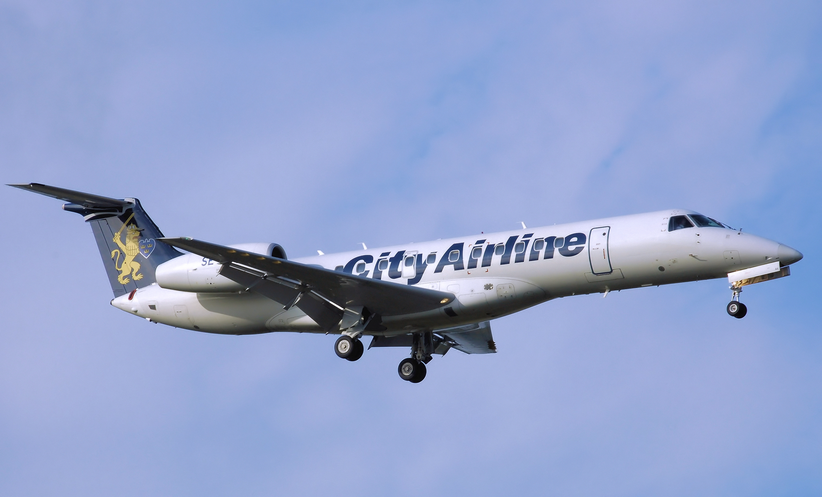
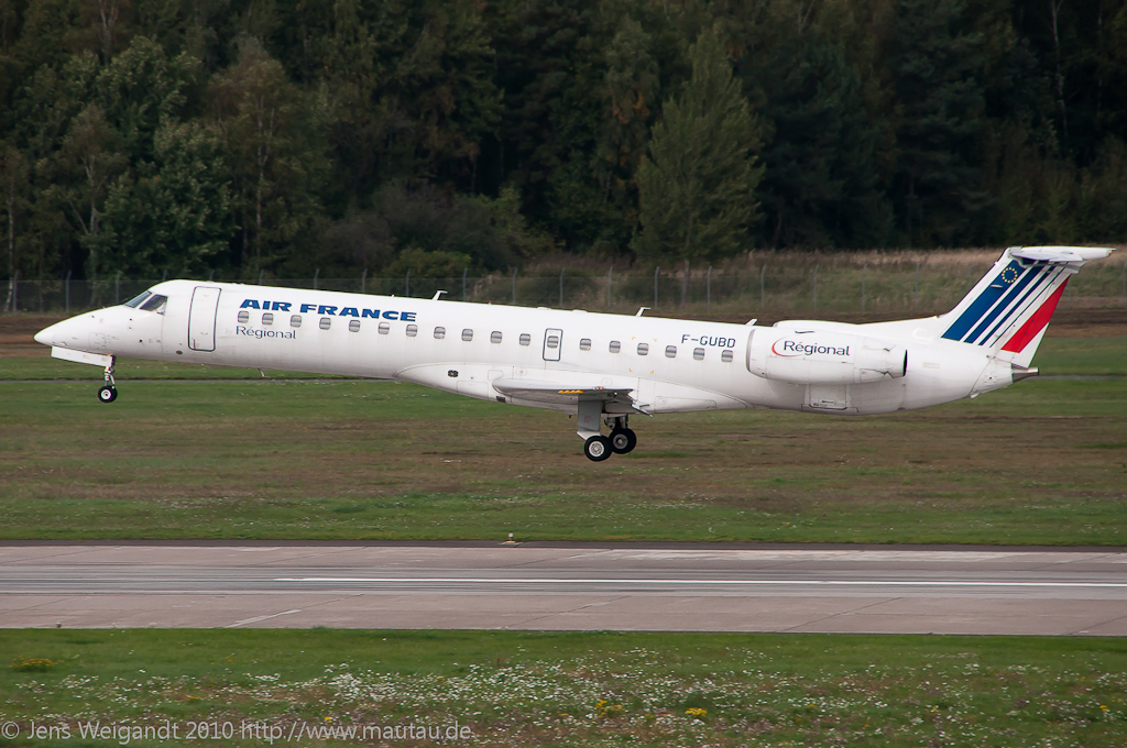
ERJ135 & 145
Illustration by By Julien.scavini - Own work, CC BY-SA 3.0, 
https://commons.wikimedia.org/w/index.php?curid=20123915

ERJ135
Photo by Adrian Pingstone (Arpingstone) - Own work, Public Domain, 
https://commons.wikimedia.org/w/index.php?curid=2707627

ERJ145
Photo by mautau - http://www.flickr.com/photos/mautau/5215696719/, CC BY 2.0, 
https://commons.wikimedia.org/w/index.php?curid=17172549

Aircraft Characteristics:
Crew: 2

Seats:
ERJ 135 ER/LR : 37
ERJ 140 ER/LR : 44
ERJ 145 LR/XR : 50

Engines: 2 x Turbo-fan

MMO:
ERJ 135 ER/LR + ERJ 140ER/LR + ERJ 145LR : M.78
ERJ 145 XR : M.80

MTOW:
ERJ 135 ER : 19,000 kg (41,887 lb)
ERJ 135 LR : 20,000 kg (44,092 lb)
ERJ 140 ER : 20,100 kg (44,312 lb)
ERJ 140 LR : 21,100 kg (46,517 lb)
ERJ 145 LR : 22,000 kg (48,501 lb)
ERJ 145 XR : 24,100 kg (53,131 lb)

Service Ceiling: 37,000 ft (11,278 m)

Range with full load:
ERJ 135 ER : 1,300 nm
ERJ 135 LR : 1,750 nm
ERJ 140 ER : 1,250 nm
ERJ 140 LR : 1,650 nm
ERJ 145 LR : 1,550 nm
ERJ 145 XR : 2,000 nm

Wingspan: 20.04 m (65 ft 9 in)

Length:
ERJ 135 ER/LR : 26.33 m (86 ft 5 in)
ERJ 140 ER/LR : 28.45 m (93 ft 4 in)
ERJ 145 LR/XR : 29.87 m (98 ft 0 in)

Engine Variants:
ERJ 135 ER/LR + ERJ 140ER/LR + ERJ 145LR : RR AE3007-A1/3 or A3 or A1/1 or A1 or A1P
ERJ 145 XR : RR AE3007-A1E

How to identify: 
- 2 Engines mounted on aft fuselage


EMBRAER E-JETS

With the successful ERJs, Embraer embarked on a larger aircraft. (No matter how large, the largest model still smaller than an Airbus A320). Ain't they cute? : )

How to identify?
Smaller fuselage comparing to Airbus A320. There are winglets.

E-JET E170
Photo By Andre Wadman - http://www.airliners.net/photo/LOT---Polish/Embraer-ERJ-170-100LR-170LR/2091242/L/, GFDL 1.2, 
https://commons.wikimedia.org/w/index.php?curid=19909269


E-JET E175
Photo By redlegsfan21 from Vandalia, OH, United States - C-FEKD, CC BY-SA 2.0, 
https://commons.wikimedia.org/w/index.php?curid=24452422


E-JET E190
Photo By Mariordo Mario Roberto Duran Ortiz - Own work, CC BY 3.0, 
https://commons.wikimedia.org/w/index.php?curid=6727886


E-JET E195
Photo By 54north - Own work, CC BY-SA 3.0, 
https://commons.wikimedia.org/w/index.php?curid=5167502


Aircraft Characteristics:
Crew: 2

Seats:
E170 : 70 - 80
E175 : 78 - 88
E190 : 94 - 114
E195 : 106 - 122

Engines: 2 x Turbo-fan

MMO: M.82

MTOW:
E170 : 35,990 kg (79,340 lb)
E170 LR : 37,200 kg (82,000 lb)
E170 AR : 38,600 kg (85,100 lb)
E175 : 37,500 kg (82,700 lb)
E175 LR : 38,790 kg (85,520 lb)
E175 AR : 40,370 kg (89,000 lb)
E190 : 47,790 kg (105,360 lb)
E190 LR : 50,300 kg (110,900 lb)
E190 AR : 51,800 kg (114,200 lb)
E195 : 48,790 kg (107,560 lb)
E195 LR : 50,790 kg (111,970 lb)
E195 AR : 52,290 kg (115,280 lb)

Service Ceiling: 41,000 ft (12,500 m)

Range with full load:
E170 : 1,800 nm
E170 LR : 2,100 nm
E170 AR : 2,150 nm
E175 : 1,750 nm
E175 LR : 2,150 nm
E175 AR : 2200 nm
E190 : 1,850 nm
E190 LR : 2,400 nm
E190 AR : 2,450 nm
E195 : 1,600 nm
E195 LR : 2,000 nm
E195 AR : 2,300 nm

Wingspan: 
E170 / E175 : 26.0 m (85 ft 4 in)
E190 / E195 : 28.72 m (94 ft 3 in)

Length:
E170 : 29.9 m (85 ft 4 in)
E175 : 31.68 m (103 ft 11 in)
E190 : 36.24 m (118 ft 11 in)
E195 : 38.65 m (126 ft 10 in)

Engine Variants:
E170 / E175 : GE CF34-8E
E190 / E195 : GE CF34-10E

How to identify: 
- Small fuselage (Body)
- Winglets

BOMBARDIER

A Canadian company. They have a great range of products from Very Small Jet to A320 size of commercial jet. They owned the brand of LearJets, Challenger, Global for Business Aviation. And they have CRJs and C-Series for Commercial operations.

CRJ-200s
Similar look and design to Embraer's ERJs.

How to identify? By looking at the fuselage mounted engines. The cowling of the CRJs' engines are shorter and exposing the exhaust tail cone (Chrome Part) more. And they all have winglets.

CRJ-100
Photo By Arpingstone assumed (based on copyright claims). Own work assumed (based on copyright claims)., Public Domain, 
https://commons.wikimedia.org/w/index.php?curid=446365

CRJ-200
Photo By Kentaro Iemoto from Tokyo, Japan - J-AIR CRJ200ER(JA206J), CC BY-SA 2.0, 
https://commons.wikimedia.org/w/index.php?curid=23461192


Aircraft Characteristics:
Crew: 2

Seats: 50

Engines: 2 x Turbo-fan

MMO: M.81

MTOW: 24,041 kg (53,000 lb)

Service Ceiling: 41,000 ft (12,496 m)

Range with full load:
CRJ-100 ER : 1,620 nm
CRJ-100 LR : 2,003 nm
CRJ-200 ER : 1,644 nm
CRJ-200 LR : 2,004 nm

Wingspan: 21.21 m (69 ft 7 in)

Length: 26.77 m (87 ft 10 in)

Engine Variants:
CRJ-100 ER/LR : GE CF34-3A1
CRJ-200 ER/LR : GE CF34-3B1

How to identify: 
- 2 Engines mounted on aft fuselage
- Small fuselage
- Winglets
- Short Engine Cowling and exposing long engine tail cone


Bombardier CRJ700 /CRJ900 / CRJ1000

Based on the CRJ200, this is a longer version of the model. It is a popular choice for domestic / Regional market with smaller airfields.

How to identify? Same as CJR200 but with a much longer fuselage.

CRJ700
Photo By ABF - Own work, CC BY-SA 3.0, 
https://commons.wikimedia.org/w/index.php?curid=12893348


CRJ900
Photo By Rriemann - Own work, CC BY 3.0, 
https://commons.wikimedia.org/w/index.php?curid=6685500


CRJ1000
Photo By Flox Papa - Flickr: EC LJR, CRJ 1000, Air Nostrum, CC BY 2.0, 
https://commons.wikimedia.org/w/index.php?curid=14695940

Aircraft Characteristics:
Crew: 2

Seats: 
CRJ700 series : 66 - 78
CRJ900 series : 76 - 90
CRJ1000 series : 97 - 104

Engines: 2 x Turbo-fan

MMO: M.82

MTOW: 
CRJ700 : 32,999 kg (72,750 lb)
CRJ700 ER : 34,019 kg (75,000 lb)

CRJ900 : 36,514 kg (80,500 lb)
CRJ900 ER : 37,421 kg (82,500 lb)
CRJ900 LR: 38,330 kg (84,500 lb)

CRJ1000 EL : 38,995 kg (85,968 lb)
CRJ1000 : 40,824 kg (90,000 lb)
CRJ1000 ER : 41,640 kg (91,800 lb)

Service Ceiling: 41,000 ft (12,496 m)

Range with full load:
CRJ700 : 1,092 nm
CRJ700 ER : 1,378 nm

CRJ900 : 1,070 nm
CRJ900 ER : 1,317 nm
CRJ900 LR : 1,553 nm

CRJ1000 EL : 971 nm
CRJ1000 : 1,425 nm
CRJ1000 ER : 1,622 nm

Wingspan: 
CRJ700 series : 23.2 m (76 ft 3 in)
CRJ900 series : 24.9 m (81 ft 7 in)
CRJ1000 series : 26.2 m (85 ft 11 in)

Length: 
CRJ700 series : 32.3 m (106 ft 1 in)
CRJ900 series : 36.2 m (118 ft 11 in)
CRJ1000 series : 39.1 m (128 ft 5 in)

Engine Variants:
CRJ700 series : GE CF34-8C5B1
CRJ900 series : GE CF34-8C5
CRJ1000 series : GE CF34-8C5A1

How to identify: 
- 2 Engines mounted on aft fuselage
- Small fuselage
- Very long fuselage
- Winglets
- Short Engine Cowling and exposing long engine tail cone

ATR

Aerei da Trasporto Regionale (ATR) is a French-Italian OEM based in Toulouse, France.

ATR72 series

This product is gaining ground in Asia Pacific as it is cheap too operate for short sectors. Speed is not fantastic for Turbo-props but for short sector this could be some good trade-off.

How to identify?
Twin Turbo-Prop, black wing boots, very low ground clearance, Landing gear retraction at the belly.

ATR-72-202
Photo By Konstantin von Wedelstaedt - Gallery page http://www.airliners.net/photo/LOT---Polish/ATR-ATR-72-202/2020929/LPhoto http://cdn-www.airliners.net/aviation-photos/photos/9/2/9/2020929.jpg, GFDL 1.2, 
https://commons.wikimedia.org/w/index.php?curid=26809222

ATR-72-200
Photo by Public Domain, https://commons.wikimedia.org/w/index.php?curid=4839271

ATR-72-500
Photo By Mili99 - Own work, CC BY 3.0, 
https://commons.wikimedia.org/w/index.php?curid=11896864


ATR-72-600
Photo By Javier Bravo Muñoz - http://www.airliners.net/photo/Air-Nostrum-(Iberia/ATR-ATR-72-600-(ATR/2167364/L/, GFDL 1.2, 
https://commons.wikimedia.org/w/index.php?curid=22026245


Aircraft Characteristics:
Crew: 2

Seats: 68 -72

Engines: 2 x Turbo-props

VMO: 250 kts

MTOW: 
ATR-72-500 : 22,800 kg (50,265 lb)
ATR-72-600 : 23,000 kg (50,706 lb)

Service Ceiling: 25,000 ft (7,620 m)

Range with full load: 825 nm

Wingspan: 27.05 m (88 ft 9 in)

Length: 27.17 m (89 ft 2 in)

Engine Variants: PW PW127 M / N

How to identify: 
- 2 Turbo-props
- Black colour wing boots
- Super low ground clearance
- Gears retract into belly not engine cowlings


Aircraft Identification Guide - Boeing 767, 777 and 787

This is part 4 of the Aircraft Identification Guide - Boeing 767, 777 and 787

BOEING

B767

For people live in Asia, the B767 will be some strangers here as most of the B767 are serving the US domestic routes. It is the first Boeing Wide body Mid-long haul jets and the first glass cockpit for Boeing. It has been in service since 1981.

Boeing 767-200
Photo by Seattle Municipal Archives - Flickr: Boeing 767 over Mount Rainier, circa 1980s Item 149279 of Seattle Municipal Archives, Water Department Digitized Slides (Record Series 8200-14), CC BY 2.0, 
https://commons.wikimedia.org/w/index.php?curid=30513288

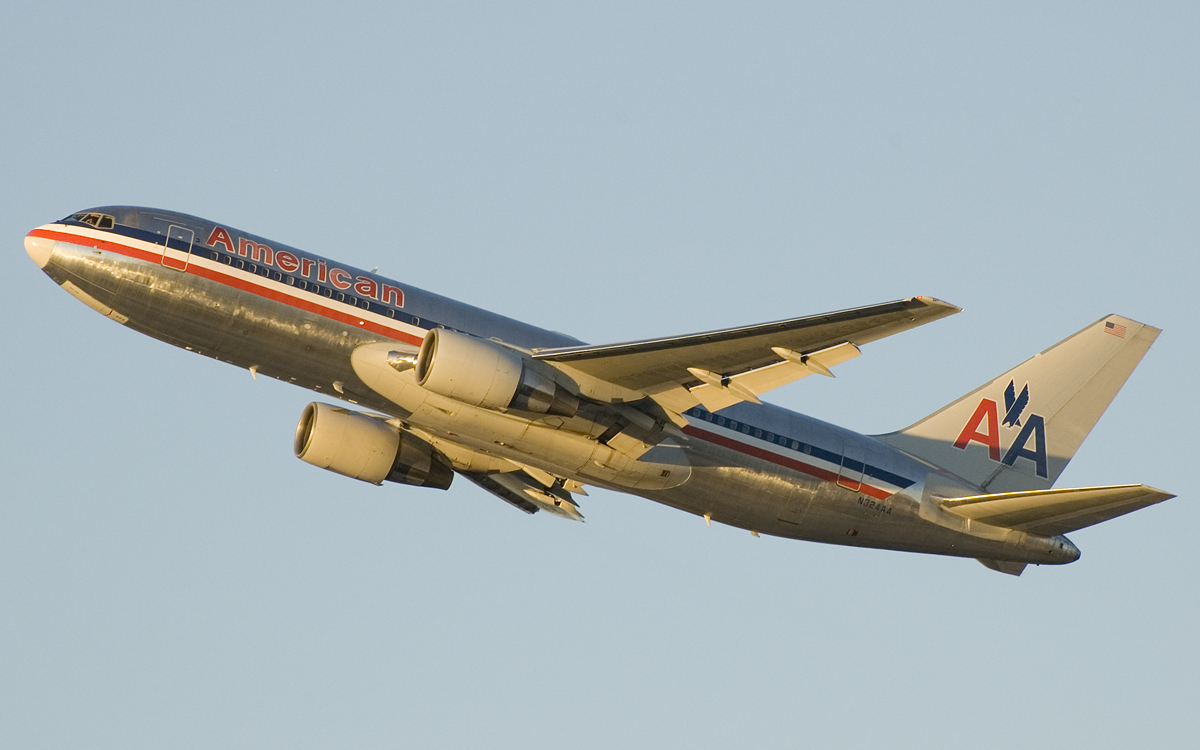
Boeing 767-200ER American Airlines
Photo by Brian from Toronto, Canada - American 767-200 N324AA, CC BY-SA 2.0, https://commons.wikimedia.org/w/index.php?curid=6720732

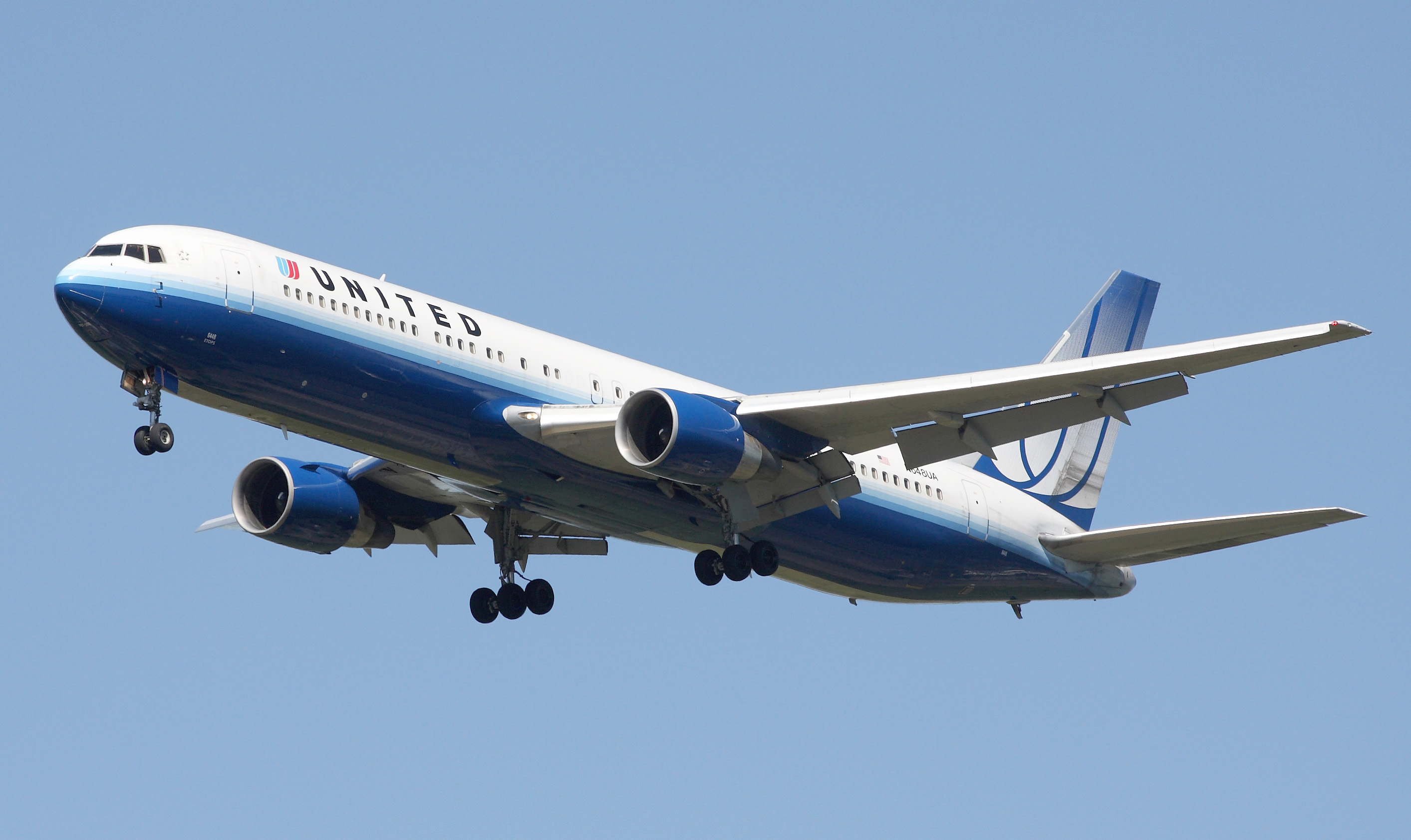
Boeing 767-300ER United Airlines
Photo By Luis Argerich from Buenos Aires, Argentina - United B767-322ER, CC BY 2.0, https://commons.wikimedia.org/w/index.php?curid=11312027

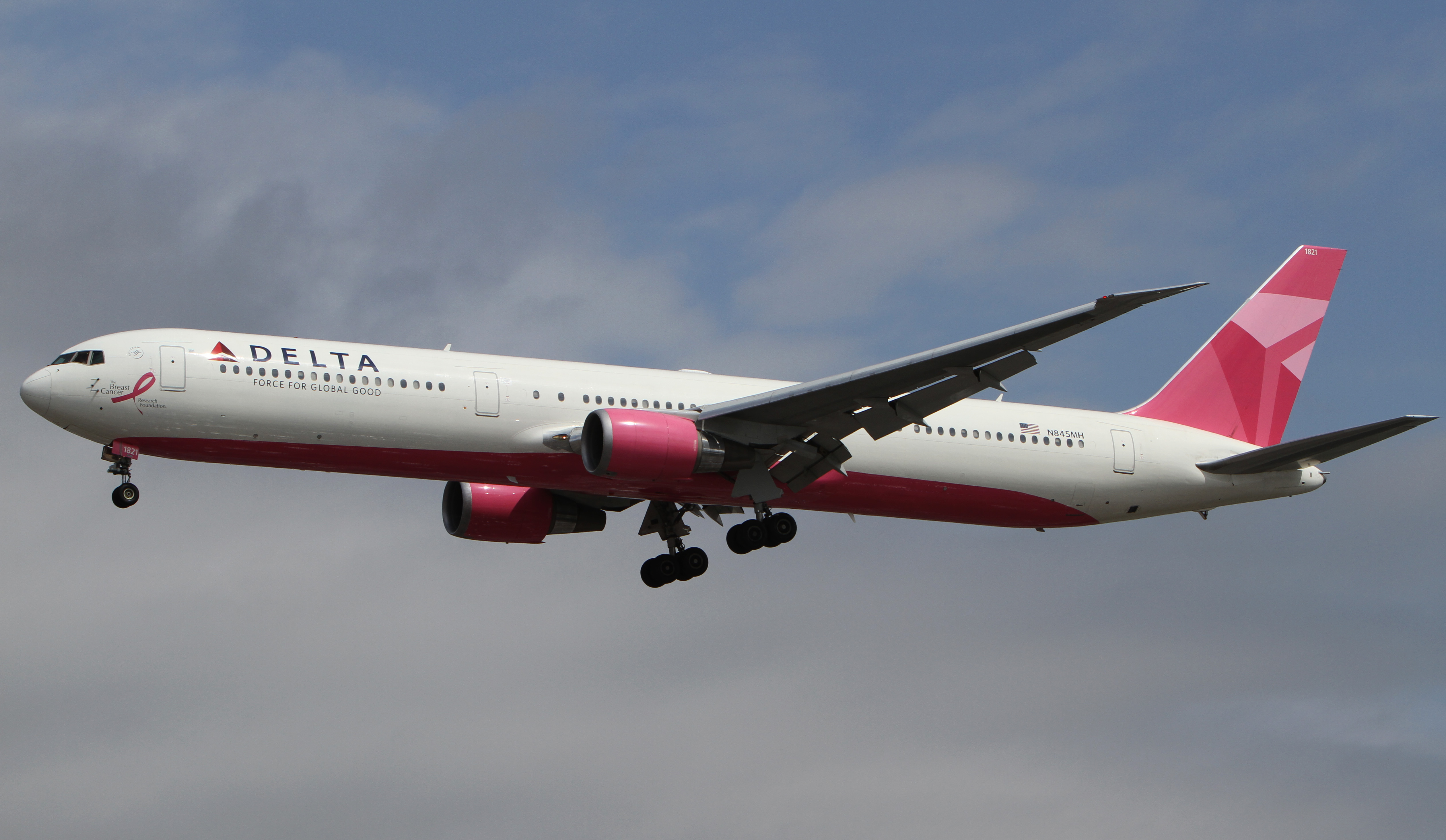
Boeing 767-400ER Delta Airlines
Photo By Martin McGrath - N845MH_DELTA_MAC_EGLL_29.05.11Uploaded by Altair78, CC BY-SA 2.0, 
https://commons.wikimedia.org/w/index.php?curid=27215835


Aircraft Characteristics:
Crew: 2

Seats:
B767-200 / 200ER : 181 - 290
B767-300 / 300ER : 218 - 351
B767-400ER : 245 - 375

Engines: 2 x Turbo-fan

MMO: M.86

MTOW:
B767-200 : 142,880 kg (315,000 lb)
B767-200ER : 179,170 kg (395,000 lb)
B767-300 : 158,760 kg (350,000 lb)
B767-300ER : 186,880 kg (412,000 lb)
B767-400ER : 204,120 kg (450,000 lb)

Service Ceiling: 41,100 ft (12,500 m)

Range with full load:
B767-200 : 3,850 nm
B767-200ER : 6,385 nm
B767-300 : 4,260 nm
B767-300ER : 5,990 nm / Winglets 6,310 nm
B767-400ER : 5,625 nm

Wingspan:
B767-200/-200ER/-300/-300ER : 47.6 m (156 ft 1 in)
B767-400ER : 51.9 m (170 ft 4 in)

Length:
B767-200/-200ER : 48.5 m (159 ft 2 in)
B767-300/-300ER : 54.9 m (180 ft 3 in)
B767-400ER : 61.4 m (201 ft 4 in)

Engine Variants:
B767-200 :
PW JT9D-7R4
PW PW4052
GE CF6-80A/A2/C2

B767-200ER :
PW PW4052/4056
GE CF6-80C2
RR RB211-524G/H

B767-300 :
PW JT9D-7R4
PW PW4052
GE CF6-80A/C2
RR RB211-524H

B767-300ER : 
PW PW4056/4060/4062
GE CF6-80C2
RR RB211-524G/H

B767-400ER : 
PW PW4062
GE CF6-80C2

How to identify: 
- 2 Engines
- No winglets for -200/-200ER/-400ER
- 2 x 4 wheels bogeys for main landing gear, 1 x 2 wheels bogey for nose landing gear
- A330 look alike but A330 have winglets


B777

The Boeing 777 is my personal favourite aircraft. It is big, has a wide cabin and powerful engines. It is very easy to identify by its unique 2 x 6 Wheels bogeys for the main landing gear. There are no winglets for the B777 as the wing tip is tapered which doesn't create much drag. The -200LR is really long range, I once flown on it from Dubai to Orlando with Flight Time 16 hours 45 minutes. 

How to identify? Look at its giant big high bypass ratio turbo-fan engine inlet. 

Boeing 777-200
Photo By Boeing Dreamscape, CC BY 2.0, 
https://commons.wikimedia.org/w/index.php?curid=12832399

Boeing 777-200ER EL AL (The unique 6 wheels bogeys)
Photo By Adrian Pingstone - Own work, Public Domain, 
https://commons.wikimedia.org/w/index.php?curid=2910760

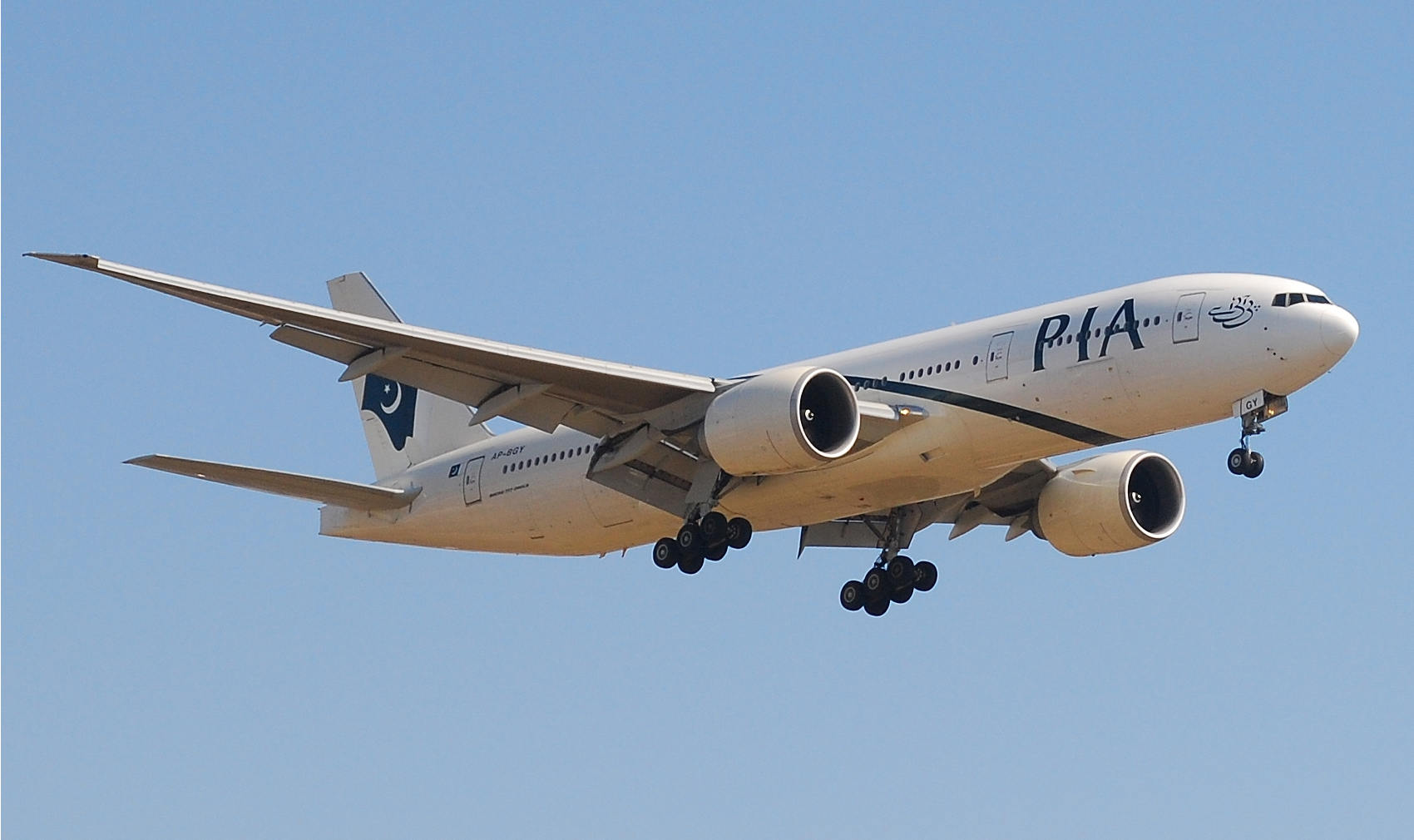
Boeing 777-200LR PIA
Photo By Ken Mist from Brampton, Canada - YYZ_AP-BGYUploaded by Altair78, CC BY-SA 2.0, 
https://commons.wikimedia.org/w/index.php?curid=6450230

Boeing 777-300 Emirates
 Photographed by Adrian Pingstone in November 2005 and released to the public domain. Emirates.b777-300.a6-emv.arp.jpg, Public Domain, 
https://commons.wikimedia.org/w/index.php?curid=15716585

Boeing 777-300ER Air Canada
Photo By Adrian Pingstone (Arpingstone) - Own work, Public Domain, 
https://commons.wikimedia.org/w/index.php?curid=4657928

Aircraft Characteristics:
Crew: 2

Engines: 2 x Turbo-fan

Seats:
B777-200/-200ER/-200LR : 314 - 400
B777-300/-300ER : 386 - 550

MMO: M.89

MTOW:
B777-200 : 247,200 kg (545,000 lb)
B777-200ER : 297,550 kg (656,000 lb)
B777-200LR : 347,500 kg (766,000 lb)
B777-300 : 299,370 kg (660,000 lb)
B777-300ER : 351,500 kg (775,000 lb)

Range with full load:
B777-200 : 5,240 nm
B777-200ER : 7,730 nm
B777-200LR : 9,500 nm
B777-300 : 6,005 nm
B777-300ER : 7,830 nm

Service Ceiling: 43,100 ft (13,140 m)

Wingspan:
B777-200/-200ER/-300 : 60.9 m (199 ft 11 in)
B777-200LR/-300ER : 64.8 m (212 ft 7 in)

Length:
B777-200/-200ER/-200LR : 63.7 m (209 ft 1 in)
B777-300/-300ER : 73.9 m (242 ft 4 in)

Engine Variants:
B777-200:
PW PW4077
RR Trent 877
GE GE90-77B

B777-200ER:
PW PW4090
RR Trent 895
GE GE90-94B

B777-200LR:
GE GE90-110B1
GE GE90-115B1

B777-300:
PW PW4098
RR Trent 892
GE GE90-92B/94B

B777-300ER:
GE GE90-115B1

How to identify: 
- Big cabin cross section
- Wide body
- Huge engine inlet
- 6 wheels bogeys for the main landing gears

B787

The Boeing 787 dreamliner will be getting more and more popular. I could mistaken as the Airbus A350 XWB as they are the direct competitor.

How you can identify one is by look at the cockpit windows - Another cool looking cockpit windows design which looks like a pair of sunglasses. Otherwise look at the engine cowling you can see the saw tooth design.

Boeing 787-8 Thomson Airways
Photo By Björn Strey - IMG_6739, CC BY-SA 2.0, 
https://commons.wikimedia.org/w/index.php?curid=26606339


Boeing 787-9 Air New Zealand (Remarkable livery)
Photo By Darren Koch - http://www.airliners.net/photo/Air-New-Zealand/Boeing-787-9-Dreamliner/2508899/L/, GFDL 1.2, 
https://commons.wikimedia.org/w/index.php?curid=37276130

Aircraft Characteristics:
Crew : 2

Engines : 2 x Turbo-fan

Seats:
B787-8 : 242 - 381
B787-9 : 290 - 420

MMO : M.90

MTOW:
B787-8 : 228,000 kg (502,500 lb)
B787-9 : 253,000 kg (557,000 lb)

Range with typical load:
B787-8 : 7,355 nm
B787-9 : 7,635 nm

Service Ceiling : 43,000 ft (13,100 m)

Wingspan : 60.1 m (197 ft 3 in)

Length:
B787-8 : 56.7 m (186 ft 1 in)
B787-9 : 62.8 m (206 ft 1 in)

Engine Variants:
GE GEnx-1B
RR Trent 1000

Boeing 787 - Saw tooth engine cowling with thrust reverser and ground spoilers activated
Photo By Eric Prado - Own work, CC BY-SA 3.0, 
https://commons.wikimedia.org/w/index.php?curid=15803415

How to identify: 
- Sunglasses look alike cockpit windows
- No winglets and has a flexi-wings (High bend angle)
- Saw tooth shape engine cowling
- 2 x 4 wheels bogeys for main landing gears + 1 x 2 wheels bogeys for nose landing gear