In Part 1 we cover most of the important control, they are:
Ailerons
Rudder
Elevators
Here in Part 2 I will continue in other control surfaces.
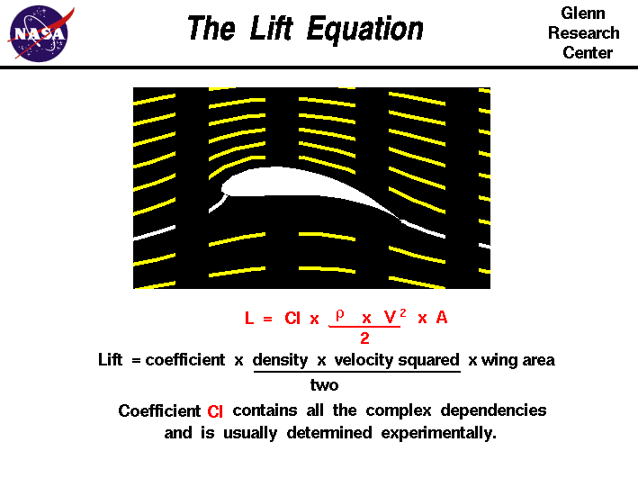
Before that I shall introduce this formula to you - The Lift Equation (Extracted from NASA. (https://www.grc.nasa.gov/www/k-12/airplane/lifteq.html)

Lift is generated based on these factors.
Coefficient - It is based on Wind Tunnel Testing and Simulation to derive the lift coefficient for each wing design.
Density - It is referring to the air density. The higher the altitude the lower the density. Just picture this (Refer to the previous Part 1 video). The higher the density the more molecules in the air.
Velocity - The speed relative to the airflow
Wing Area - Self explanatory. You might think that "Let's make the biggest wing and will produce more lift!" Yes, you are half correct but at the same time you will introduce more drag as well.
So we need to strike a balance to maintain the Lift to Drag Ratio.
The wing shape is the most crucial and costly part of the plane design, it takes billion dollars to R&D a new wing. So don't play play.
Slats & Flaps:
Slats are additional lifting devices installed on or inside the wing's leading edge. (See Fig.2)
The idea is to increase the wing camber. The slats control normally is hard wired together with the Flaps, the Slats as it has only one position and normally tied with the first flaps setting. The slats can dramatically reduce the take-off and landing distance. It helps to lower the nose, so that the pilot can have a better take-off and landing view without increasing airspeed.
Flaps are additional lifting devices installed on or inside the wing trailing edge. (See Fig.3 & 4) The idea is to increase the Wing Area and camber. The Pilot in the cockpit control the flaps by putting the Flaps into the desire slots.
Different OEM will have different calling. Boeing will have the flaps settings in °; e.g. 1°, 5°, 15°, 30°, 40° while Airbus will have the setting in number. e.g. Flaps 1, 2, 3, Full.
Control:
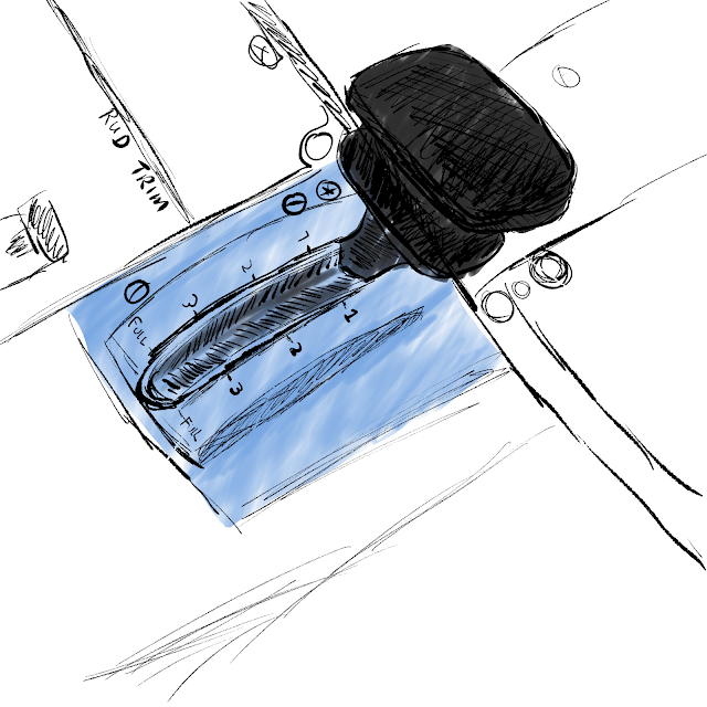
The control is located inside the cockpit (See Fig.5 & 6 - Airbus A320) normally on the central pedestal. And it is control by a stick with different position settings. The pilot have to observe the designed extension and retraction speed of the flaps. e.g. when the airspeed over the Vfe, the flaps might be damaged by strong speed.
Effect on flying:
When the slats and flaps are extended, the aircraft will tend to ascend due to the extra lift and hence the pilot will have to push the yoke to lower the nose. The benefit of this will give the pilot a better field of view for their take-off and landing.
Normally, during take-off the flaps setting will be 1 or 2 because 3 onward though give you more lift but it also create more induce drag.
During landing the extra drag is actually plus points therefore they will normally use Flaps 3 or Full for landing.
Trims:
Imagine when you are flying an aircraft and you have to hold on to the yoke or side stick for minutes, that is a very tiresome move and it stresses the pilot physically. Therefore the solution is trim. (See fig.7)
There are three trim tabs installed on Elevators, Ailerons, and Rudders. (See picture) The trim tab is adjusted by a trim wheel, or switch installed in cockpit to adjust to the desire outcome. With that the pilot is able to fly the plane "hands-free". Do take note that during take-off and landing, you have to adjust the trim back to the acceptable trim range. In case of emergency, if your trim is not within the acceptable range, the plane will not response enough to your desire input.
Engines a.k.a. Power Plants:
Without engines the plane will not fall out of the sky but the plane will become a giant glider. The engine is important to produce power to either push or pull the plane forward. That resulted in the Lift Formula "V" component. The faster it is the more lift it can generates.
Engine configurations are many, like single piston propeller to supersonic jet engine. In terms of efficiency, the piston or turbo propeller configuration is more suitable for lower altitude (1000 ft to FL280) range.
The Jet engine is more efficient in higher altitude (FL250 - FL510) because of low air density (low drag, high rpm).
There are single, twin, triple and quad engines configurations. In these days twin engines configuration is the norm due to increase engine reliability and fuel-consumption friendly.
Flight Control:
In airliner, the engine is govern by 2 x FADEC (Full Authority Digital Engine Control) computer and is 100% digital control (No more mechanical wires and cables).
In a turbo-fan engine we have measurement from N1 & N2 and they are measured in terms of percentage.
N1 is talking about stage 1 fan speed and N2 is talking about compressor stage fan speed. The throttle quadrant is the pilot input to control the fan speed.
In modern day airliners, speed control is by the FCS (Flight Control System) also part of the Auto-pilot. The pilot just need to input the desire speed and the FADEC will control the engine to the required speed.
I have over simplified things here but maybe in future I will dedicate one single session about power plant.
During all sorts of control failures, and left only with engines control you can still control the plane by adjusting engine power.
To climb, just add more power to the engine.
To descend, just reduce power.
To turn left, just increase starboard side power and reduce port side power.
To turn right, do the opposite.
Ailerons
Rudder
Elevators
Here in Part 2 I will continue in other control surfaces.
Before that I shall introduce this formula to you - The Lift Equation (Extracted from NASA. (https://www.grc.nasa.gov/www/k-12/airplane/lifteq.html)

Lift is generated based on these factors.
Coefficient - It is based on Wind Tunnel Testing and Simulation to derive the lift coefficient for each wing design.
Density - It is referring to the air density. The higher the altitude the lower the density. Just picture this (Refer to the previous Part 1 video). The higher the density the more molecules in the air.
Velocity - The speed relative to the airflow
Wing Area - Self explanatory. You might think that "Let's make the biggest wing and will produce more lift!" Yes, you are half correct but at the same time you will introduce more drag as well.
So we need to strike a balance to maintain the Lift to Drag Ratio.
The wing shape is the most crucial and costly part of the plane design, it takes billion dollars to R&D a new wing. So don't play play.
Slats & Flaps:
Slats are additional lifting devices installed on or inside the wing's leading edge. (See Fig.2)
The idea is to increase the wing camber. The slats control normally is hard wired together with the Flaps, the Slats as it has only one position and normally tied with the first flaps setting. The slats can dramatically reduce the take-off and landing distance. It helps to lower the nose, so that the pilot can have a better take-off and landing view without increasing airspeed.
Flaps are additional lifting devices installed on or inside the wing trailing edge. (See Fig.3 & 4) The idea is to increase the Wing Area and camber. The Pilot in the cockpit control the flaps by putting the Flaps into the desire slots.
Different OEM will have different calling. Boeing will have the flaps settings in °; e.g. 1°, 5°, 15°, 30°, 40° while Airbus will have the setting in number. e.g. Flaps 1, 2, 3, Full.
 |
| Fig. 1-4 Showing varies stages of Slats and Flaps configurations |
The control is located inside the cockpit (See Fig.5 & 6 - Airbus A320) normally on the central pedestal. And it is control by a stick with different position settings. The pilot have to observe the designed extension and retraction speed of the flaps. e.g. when the airspeed over the Vfe, the flaps might be damaged by strong speed.
 |
| Fig.5 - Airbus A320 Cockpit |
 |
| Fig.6 - A320 FLAPS Lever |
When the slats and flaps are extended, the aircraft will tend to ascend due to the extra lift and hence the pilot will have to push the yoke to lower the nose. The benefit of this will give the pilot a better field of view for their take-off and landing.
Normally, during take-off the flaps setting will be 1 or 2 because 3 onward though give you more lift but it also create more induce drag.
During landing the extra drag is actually plus points therefore they will normally use Flaps 3 or Full for landing.
Trims:
Imagine when you are flying an aircraft and you have to hold on to the yoke or side stick for minutes, that is a very tiresome move and it stresses the pilot physically. Therefore the solution is trim. (See fig.7)
 |
| Fig. 7 - Trim tabs (Tail view) |
There are three trim tabs installed on Elevators, Ailerons, and Rudders. (See picture) The trim tab is adjusted by a trim wheel, or switch installed in cockpit to adjust to the desire outcome. With that the pilot is able to fly the plane "hands-free". Do take note that during take-off and landing, you have to adjust the trim back to the acceptable trim range. In case of emergency, if your trim is not within the acceptable range, the plane will not response enough to your desire input.
 |
| Fig. 8 - Trim tab in action. It is adjusted by trim wheel in cockpit |
Engines a.k.a. Power Plants:
Without engines the plane will not fall out of the sky but the plane will become a giant glider. The engine is important to produce power to either push or pull the plane forward. That resulted in the Lift Formula "V" component. The faster it is the more lift it can generates.
Engine configurations are many, like single piston propeller to supersonic jet engine. In terms of efficiency, the piston or turbo propeller configuration is more suitable for lower altitude (1000 ft to FL280) range.
The Jet engine is more efficient in higher altitude (FL250 - FL510) because of low air density (low drag, high rpm).
There are single, twin, triple and quad engines configurations. In these days twin engines configuration is the norm due to increase engine reliability and fuel-consumption friendly.
Flight Control:
In airliner, the engine is govern by 2 x FADEC (Full Authority Digital Engine Control) computer and is 100% digital control (No more mechanical wires and cables).
In a turbo-fan engine we have measurement from N1 & N2 and they are measured in terms of percentage.
N1 is talking about stage 1 fan speed and N2 is talking about compressor stage fan speed. The throttle quadrant is the pilot input to control the fan speed.
In modern day airliners, speed control is by the FCS (Flight Control System) also part of the Auto-pilot. The pilot just need to input the desire speed and the FADEC will control the engine to the required speed.
I have over simplified things here but maybe in future I will dedicate one single session about power plant.
During all sorts of control failures, and left only with engines control you can still control the plane by adjusting engine power.
To climb, just add more power to the engine.
To descend, just reduce power.
To turn left, just increase starboard side power and reduce port side power.
To turn right, do the opposite.
No comments:
Post a Comment